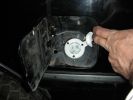
120V, 20A charge port3861 viewsAs you can see, it has the sideways prong to only allow a 20A rated cord to plug into it.
I'll carry an adapter for those times I need to plug into a 15A or less outlet.May 15, 2009
|
|
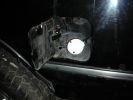
120v, 20A charge port3607 viewsThis is the 120V, 20A charge port.May 15, 2009
|
|
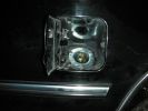
240v charge port3126 viewsMay 15, 2009
|
|
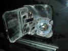
240V, 50A charge port5135 viewsThis is the 240V 50A charge port with a jack for a CS6364 plug.May 15, 2009
|
|
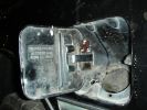
Charge Port Door switch5542 viewsThis shows how I mounted a switch on each of the charge port doors. (used to be gas tank doors!)
This switch will tell the Z2K controller if either of the charge port doors is open, and if so, it won't let the truck "start".
Really helpful to prevent driving off with the cord still plugged in.May 15, 2009
|
|
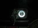
240v charge port3141 viewsMay 15, 2009
|
|
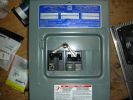
Breaker Box (again)3252 viewsMay 15, 2009
|
|
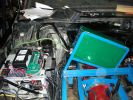
PFC mount4715 viewsThis shows how the PFC 50 charger is mounted under the hood.
It's at an angle so that I can easily reach the controls.
The 2 meters in the wiring station are a 50A AC Ammeter, and a 300V AC Voltmeter. Useful for adjusting the charger for whatever I happen to be plugged in to.May 15, 2009
|
|

Breaker Box w/mechanical interlock6274 viewsThis is the breaker box that is mounted on the truck. It has a 240V, 50A GFCI breaker, and a 20A 120V (dual) breaker.
Each breaker enables one of the charge ports. Only 1 can be "on" at a time due to the rather simple mechanical interlock.May 15, 2009
|
|
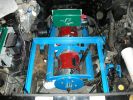
Motors Wired4258 viewsI wired the motors to the Z2K using 4/0 cable.
Notice that I don't like exposed High Voltage connections. Couldn't do much about the 1000A shunt though.Apr 29, 2009
|
|
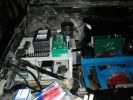
Central Wiring area4131 viewsThis is where most of the control wiring will be.
It's not done yet in this photo.
The meters are the AC Amps and Volts for the PFV-50 input.Apr 29, 2009
|
|

Mechanical link between Breakers3735 viewsThis shows how I made it so that only 1 of the 2 power inlet breakers can be ON at a time.
Both can be off, but only 1 can be ON.Apr 13, 2009
|
|
| 118 files on 10 page(s) |
 |
3 |  |
 |
 |
 |
 |
 |
|